2016-12-13

Seasonal Blinkenlights

Recently, my wife complained about being bored by all the monochrome Christmas displays in the neighborhood. "Can't we have something gaudy?" she asked.

Being cheap and lazy, I remembered that I had an addressable 1m LED strip that I bought several years ago and never really tried for anything interesting. After a night's hacking, I came up with a few different animations:


High art, it is not, but I picked up some new ideas, especially about how to sort colors.

I also learned that these strips have highly variable builds. Not only were the colors of the wires completely different from their documentation (but easy to figure out from the physical layout), but even the colors of the LEDs were hooked up in a different order than the WS2801 data sheet would have implied.

The code is fairly trivial, but given the reaction of my wife and sons, I think I got a pretty good return on those 450 lines of code.

2016-06-25

Light & Ladder — Simple Testbed for Microcontrollers

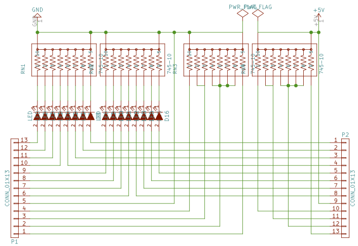
Recently I was bringing up an Arduino-like core for the ATtiny841, and wanted to test all the functionality. Testing digitalOut and analogOut was simple, though doing so for lots of pins required a bit of setup. digitalIn was also simple, but analogIn required slightly more work. As a small exercise, I decided to combine all of the required parts onto a single board. Using integrated resistor networks helped save a lot of parts.

The top part is very conventional, but the bottom might be a bit more interesting. Effectively, it serves as a primitive analog computer to generate a wide selection of fractions of the voltage applied to "+" and "-". As noted on the board, connecting one or more pins from the "+" side to one or more pins from the "-" side generates a voltage V*P/(P+M) where "P" is the sum of the labels of pins connected on the "+" side and "M" the sum on the "-" side. If "+" is 5V, you can obtain e.g.:
  • 1V as 1/5 of 5V, by connecting "1" on the "+" side and "4" on the "-" side.
  • 1.25V as 1/4, by connecting "1" on the "+" side, and 3 (as "1" and "2") on the "-" side.
  • 1.5V as 3/10, by connecting "1" and "2" on the "+" side, and "1", "2", and "4" on the "-" side.
Source code available on Github, boards on OSH Park.

2016-05-08

Announcing Octarine

Announcing Octarine — Electronic Component / Data Sheet Manager

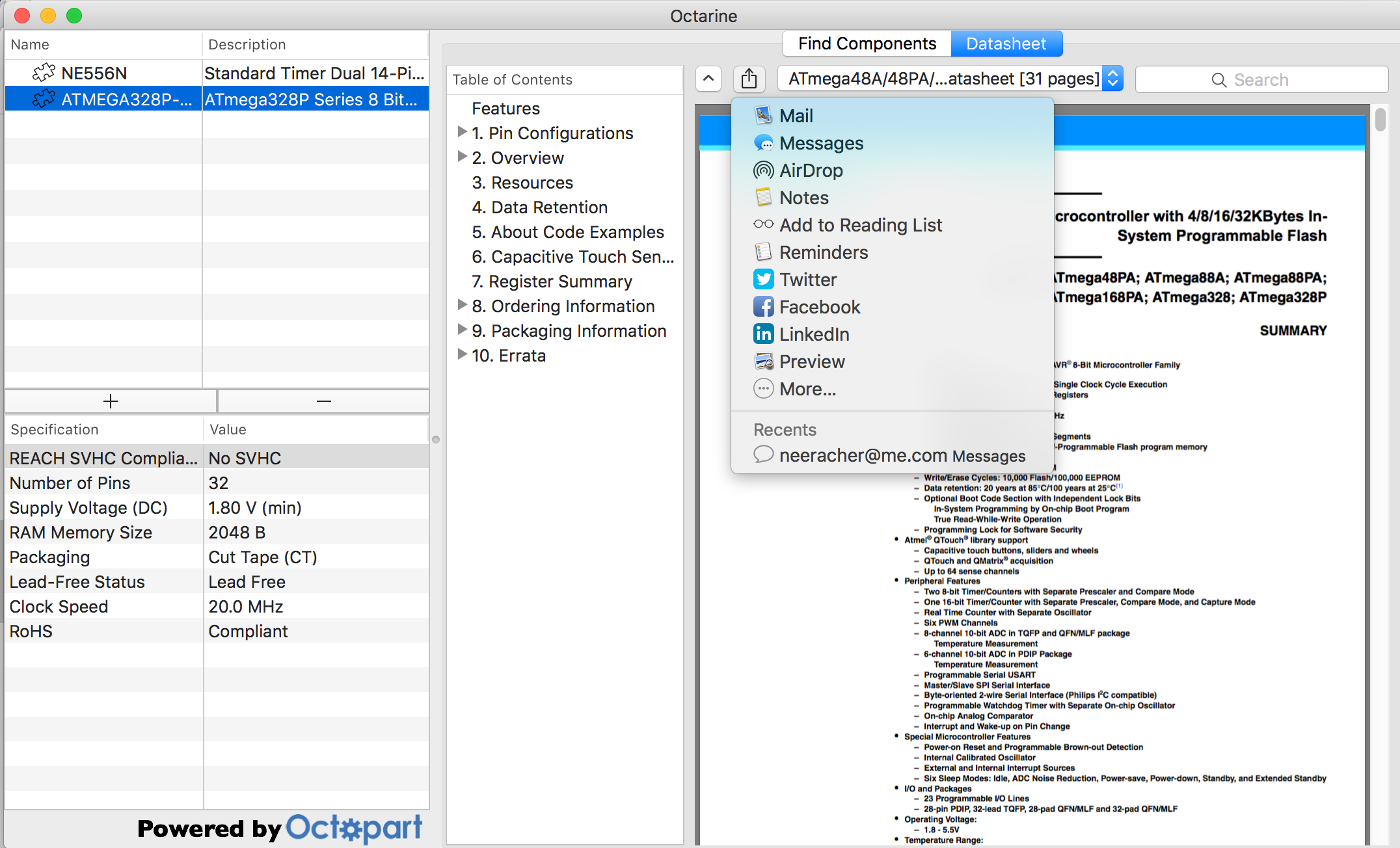
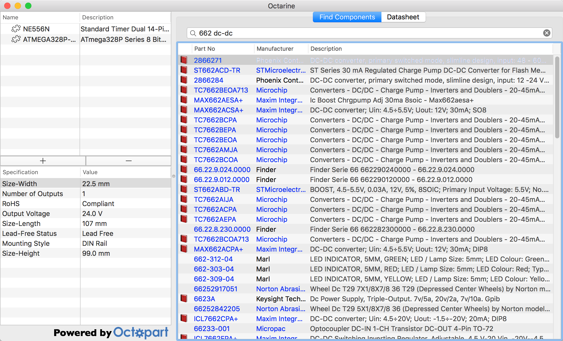
Having acquired a sizable collection of parts by now, I often find myself wasting time browsing for data sheets over and over again, instead of having them ready when I need them. I decided to remedy the situation by writing an app, Octarine, to manage my components. Building on the REST API offered by octopart.com, I tried to minimize the amount of information stored locally, and fetch everything else on the fly.

Octarine 1.5 is now available on github, running on OS X 10.10 (Yosemite) or later.

As usual with my hobby projects, this was an opportunity to try a few technologies I don't use much in my day job:

  • Swift.
  • NSURLRequest
  • PDFKit
  • NSSharingService
Component search in the Octopart database (right). Saved components (left)
Data sheet viewer

2015-08-16

Introducing AutoISP - In-Circuit Reprogramming Made Simple

This week, I was honored to see my AutoISP family of boards being put into actual commercial production by Boxtec.


AutoISP is designed to help those among us ATtiny programmers who don't write perfect software on the first iteration. Previously, our alternatives were:

  • Pull the microcontroller from the board, plug it into a programmer, reprogram it, pull it from the programmer, and plug it back into the board.
  • Make the programming pins accessible on the board (e.g. with IC hooks or by adding an ICSP header to the board). This may limit the use to which those pins can be put otherwise (and sparing 4 data pins on an ATtiny85 for programming is rarely an attractive proposition).
AutoISP solves this problem by placing the microcontroller itself on a slave board which is plugged into a socket on the circuit to be developed. The AutoISP master board then employs an STMAV340TTR 4PDT "video switch" to switch between two states:
  • If the RESET pin on its ICSP header is HIGH (or not connected), all pins on the microcontroller are connected to the development circuit, as if the microcontroller were plugged into the circuit directly.
  • If the RESET pin goes LOW, the MOSI, MISO, RESET, and SCK pins on the microcontroller get disconnected from the development circuit and connected to the ICSP header on the master board instead, which allows the microcontroller to be reprogrammed.
This makes it possible to use AutoISP transparently with most ISP programmers (e.g. the ArduinoISP sketch or ScratchMonkey), as long as those programmers leave VCC turned on while not programming. With the exception of the RESET pin, all other pins of the microcontroller are available for unrestricted use.


All electronic are placed on the master board, while the slave boards merely have sockets and pin headers. At the moment, slave boards are available for the ATtinyX5 (25/45/85), ATtinyX4 (24/44/84) and ATmegaX8 (88,168,328) series, although the approach is applicable to any ATtiny or ATmega processor.

Detailed circuits are available on Github and in the AutoISP manual.


2015-04-20

Introducing ChipHeadBang

There are a number of widely used methods to connect microcontroller projects to USB, all of which are not entirely satisfactory:

  • The commonly used FTDI chips are somewhat expensive, and their manufacturer has made some unpopular decisions with their driver support (although technically, the FTDI drivers work quite well).
  • Atmel also offers microcontrollers with built in USB, but those also tend to be a bit expensive.
  • Software USB stacks use a considerable proportion of the microcontroller's processing power, and as not always as reliable as hardware solutions.
When I therefore heard about a very cheap (40 cents a piece) USB to serial converter IC, the WinChipHead CH340G, I was eager to try it, and bought a few (I bought mine on AliExpress, but they are now also available at Boxtec). A prototype I built on a breadboard worked reasonably well, so I decided to try my hand at a custom PCB design:


To a large part, this follows a reference design from the vendor datasheet, using an Eagle part made by blogger [Ian]. I added a few customizations:

  • Boxtec's Christoph Schneeberger successfully convinced me to include a fuse. Though one might suspect a nefarious plot to sell more fuses, he'd probably make a bigger profit selling replacement parts for melted down unprotected boards (not to speak of potentially frying the USB port of a laptop).
  • I added LEDs on the RX and TX lines. Since serial lines are high when quiescent, I made them active low.
  • I put an ICSP header on the board so it could easily also be used as a bitbang programmer.
In many ways, the resulting design was a bit more complex than what I had done before: It's my first design involving an USB connector, and it uses more SMD parts (12) than any of my previous designs. I was therefore quite pleased when I managed to assemble my first copy of it with relatively little drama, and the functionality worked as designed (As usual, my application of solder paste for the CH340 was somewhat uneven, so I had to fix some shorts and one flaky pin connection). The serial connection seems to work even at high rates, and the bitbang programming works at the stately pace of about 1.2KB per minute.

I should mention that the CH340 has its drawbacks: Documentation is hard to find, especially if you don't speak Chinese. Driver support is iffy: My understanding is that the Linux and BSD drivers are OK, but the Windows and Mac drivers are not properly signed, and the Mac drivers will actually cause kernel panics on the latest versions of OS X. I was quite satisfied with quality of the commercial third party OS X driver I ended up buying, and the price is very reasonable, but if building a cheap solution was the objective in the first place, even that reasonable price does of course spoil the economics (if not the hedonics) of the exercise.

UPDATE: Thanks to the codebender team, there is now a working free Mac driver for CH340 again, even a properly signed one.

Design files available on Github: https://github.com/microtherion/ChipHeadBang

2015-04-05

Introducing Quarantatre

I might as well retitle my blog "The Art of the Blink Sketch", but this one has a bit of a twist:


The Quarantatre is a breakout board for the ATtiny43U microcontroller (basically just an implementation of the reference design shown in the AVR188 application note, though I did not follow the component layout recommendations all that closely).

In addition to the typical features found in other ATtiny models, the ATtiny43U has a built in boost converter allowing it to not only run off a single AA or AAA battery, but even to generate a regulated 3V voltage. While this only allows for a small current draw (apparently the limit is around 30mA), this could potentially be interesting for some applications.

The boost converter needs a few external components to work, and some of them, especially the Schottky diode, are not really available in breadboard friendly variants, so to truly test the boost converter, I had to make this custom PCB (available for ordering at OSH Park, design files on Github).

As usual, I've made an Arduino-style core available on Github at https://github.com/microtherion/arduino-tiny1634-43u (migrating from Google Code, which is shutting down). The standard Arduino tool chain probably won't support it; as always, I recommend CrossPack-AVR for OS X.

2014-11-28

A Sophisticated Heat Beam Which We Called a "Laser."

Having recently acquired a stylish collection of potentiometers and knobs from Tayda2009, I wanted to mount them in a mechanically solid way. An excellent opportunity to learn how to use the Epilog laser cutter at FabLab Zürich

I started with a box design built at MakerCase, rearranged the pieces to fit an A4 sheet of poplar plywood, and added the other features (cutouts for the potentiometer shafts and wires, outline for the breadboard, etc) to the top surface.

After struggling unsuccessfully with Inkscape (which was not overly fond of the 0.01mm thickness of lines signaling to the laser cutter to cut instead of rasterizing, and created PDFs that omitted all circles with that thickness), I spent a well invested dollar on EazyDraw 3 (there appears to be a separate app for every version from 3 to 7, with prices neatly staggered, which I didn't know when I bought the oldest one, but it was perfectly suitable for my purposes) and redid the SVG, creating a PDF that opened just fine.


15 minutes' or so worth of cutting and rasterizing got me this: 


The design has a number of flaws (a.k.a teaching moments for next time):

  • I left off the bottom surface, because it would have been useless, but I forgot to adjust side surfaces to remove the fingers for the bottom. Oh well, I'll pretend these were meant for ventilation.
  • The box is considerably deeper than it needs to be. 2cm would have been ample, I made it twice as deep.
  • The potentiometers I bought have a little pin at the edge, which I had not noticed. In order to be able to mount them flush, I had to cut small notches for those pins, which luckily was no problem with the plywood.
  • The hole for the wires are a bit close to the potentiometer shaft hole, as the pins of the potentiometer are fairly long. On the other hand, there's no reason why the pins of the potentiometer have to point in any particular direction (the knob will mount in any orientation),   so I might just cut the pin notches so the potentiometers are facing at a 45 degree angle to the wire hole next time.
Overall, though, I'm pleased with the result, shown here demonstrating three simple audio circuits (On the left, a VCO and a Metronome, using the two timers of a 556. On the right, a non-functional attempt to build an OpAmp based circuit driving a piezo element).