Materials
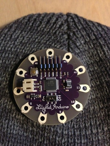
Boxtec carries a reasonable selection of LilyPad compatible boards to get started. In particular the ProtoSnap LilyPad development board contains all the electronics used in this project, except for the colored LEDs, and also comes with a 110mAh LiPo battery, the conductive thread needed to connect everything, and an FTDI board for the USB connection (No separate charger for the battery is needed; the battery will charge when the LilyPad is connected to USB).
Pretty much any hat should be OK for this project; the one I picked turned out to be a bit on the small side for the customer, and picking a color so close to the color of the conductive thread was not as clever a decision as I had originally thought.
Layout
I started out by installing the LilyPad Simple processor board on the inside of the hat, at the very top, and a temperature sensor on the outside, at the top (The temperature sensor is not currently used, although I got it to work to some extent; more on this in a separate post).
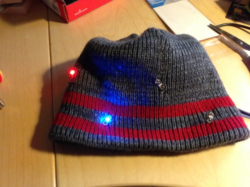
The LEDs are arranged in two staggered rings of 4 LEDs each, red on top, and alternating blue/green on the bottom.
Sewing the Connections
This was the true challenge in this project. I may have learned a little bit of sewing as a child, but hadn't held a needle in more than 25 years. However, this Instructable on Sewing was quite helpful, and entirely sufficient to get the project done.
Initially, I started with a planned pin assignment for the LEDs, but it turned out to be easier in some cases to stitch a connection from whatever pin was closest to the LED I wanted to connect, and adapt the code to the physical layout, rather than the other way around. Since I was not using PWM, and only one analog input, most pins were largely interchangeable for my purposes.
Writing the Code
My plan was to run the red LEDs and the blue&green LEDs separately, so I could have one LED in each group lit. To save pins, I wired up the red LEDs using a Charlieplexing scheme using 3 pins. However, when testing the result, one of the LEDs would not work cleanly, with two of its neighbors lighting up as well. Despite testing all the connections for short circuits, I was unable to find the cause. I suspected that the high impedance state might not have worked as planned, due to the peculiarities of LilyPad connections.
To test this, I wired the blue/green LEDs using 4 pins, with a simpler multiplexing scheme that did not rely on tristate logic. Ultimately, though, the results were not much better, with one of the LEDs never lighting up. I probably would have been best off with a common cathode/anode, one pin per LED scheme, but for what it's worth, my code is here.
Tying up the Loose Ends
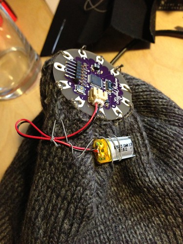
Having decided that my result was close enough to what I wanted to build, I installed the battery in place with some non-conductive thread.
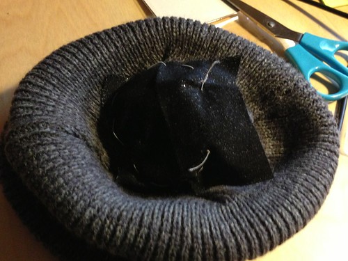
Finally, I wanted to cover up the LilyPad main board and the battery. Having the electronics in contact with someone's head seemed like a bad idea for the electronics, and the LilyPad has a rather prominent male 6 pin connector, which looked like an injury risk. A piece of black repair sheet, and some more non-conductive thread did the job reasonably well (with the opening of the stitching leaving enough space to insert the FTDI/USB board for reprogramming and recharging).
Customer Test
After some initial skepticism, my son decided that his hat was nearly as cool as a pair of LED sneakers:
Lessons Learned
- Working with conductive threat is the equivalent of building a circuit using non-insulated wires exclusively. It can be tricky to avoid short circuits.
- My idea of having most of the stitching run between the outer and inner layers of the hat made it even harder to find out what’s going on.
- It’s not clear whether the material of the hat might have been somewhat conductive itself.
- Redoing a stitched connection can be quite a bit more work than redoing a wire, especially since I tried to run a single thread through several destinations, instead of doing strictly point to point connections.
- That said, the stitching itself was not terribly difficult, as long as I was not overly fussy about the esthetics of the outcome.