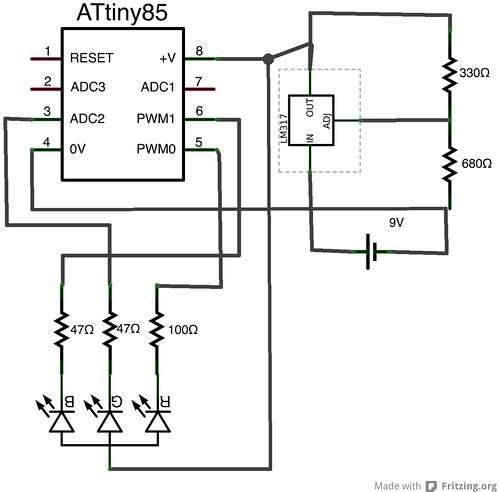
Power Supply
The RGB LED I had needed forward voltages of 3V and more, so keeping the original 2x1.5V C cell power supply was not really viable (apart from the corrosion problem), so I decided to use a 9V battery. However, 9V was outside the operating range of the ATtiny85, so I used a LM317 voltage regulator to adjust the voltage to 3.8V (comfortably within the range of the ATtiny85, close to 3.3V for experiments, and suitable for resistors I had available).
Prototyping & Programming
Breadboarding the circuit was trivial, with my new Bus Pirate serving ably as a SPI programmer.
Adding the Bus Pirate as a Programmer to the Arduino IDE is simple: In your Arduino projects folder (~/Documents/Arduino on a Mac), add a file hardware/buspirate/programmers.txt:
this will work OK, but quite slowly, as the version of avrdude shipping with current Arduino IDEs includes a suboptimal protocol for talking to the Buspirate. If you download the latest version of avrdude from its subversion repository, recompile, and copy avrdude and avrdude.conf to their corresponding paths in the Arduino IDE, it’s possible to obtain much higher programming speeds (You could also re-flash the Bus Pirate firmware to set it up for the stk500 protocol, but I would not recommend that).
While in earlier ATtiny85 experiments, I used the attiny Arduino cores, I switched to the Arduino-tiny cores this time, because attiny only supported 2 PWM pins on the ATtiny85, while Arduino-tiny supports 3.
The code itself is straightforward, except that since the LED is common anode, it is activated by a LOW output, and by the “inactive” part in the PWM cycle.
Layout
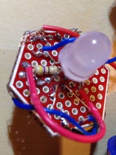
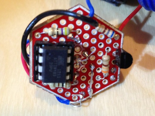
I had a SparkFun hex shaped protoboard that fit the flashlight very well. Fitting all the components onto the board was rather challenging, especially since the position of the LED in the middle of the board was not really negotiable. My original plan was to put the LED on one side and the rest of the components on the other, although this added some additional complications for the wiring.
Assembly
Despite the cramped layout, I thought I had done a pretty good job placing the components. Unfortunately, I had forgotten to include the current limiting resistors for the LED, so the LM317 failed within a few seconds. Luckily, I had a scratch monkey at hand, and the LED and the ATtiny were undamaged. Removing the failed LM317 proved rather difficult, and retrofitting resistors between the LED ATtiny even more so. Ultimately, I found it easiest to put one of the resistors on the LED side of the board.