2013-06-24

Announcing ScratchMonkey 1.0

Among the sketches bundled with the Arduino IDE is  ArduinoISP, which only becomes relevant once you buy your second Arduino or other AVR processor. ArduinoISP turns an Arduino into a programmer, communicating with avrdude on a PC through the STK500 protocol, and with a  target AVR processor through an SPI based protocol (known as In-System Programming a.k.a ISP).

Earlier this year, I decided to expand on this idea, and ended up writing ScratchMonkey, a more versatile programmer sketch emulating the STK500v2 protocol.

A Better ISP Programmer

ArduinoISP is perfectly well suited for programming other Arduinos, or many AVR processors with factory fuse settings. However, the version bundled with the Arduino IDE has some limitations (some of which are addressed in forks of the standard version, to be fair):
  • Communication speed with the computer is limited to 19200 baud for protocol compatibility reasons. ScratchMonkey is emulating a newer protocol and thus runs at 115000 baud.
  • The protocol used limits flash programming to 16 bit addresses, which prevents programming the ATmega2560 used in Arduino Mega 2560s. ScratchMonkey supports the address extensions needed for larger flash memories.
  • If the fuse settings of the target processor specify an external clock source, it is necessary to supply one i.e. by installing a crystal on the bread board (this is not a problem when reprogramming Arduinos, as the board already contains a clock source). ScratchMonkey provides a clock source by generating a PWM wave on one of the timer output pins.
  • If the fuse settings specify a very slow internal clock source (e.g. the 128kHz internal source available on some processors), or a slow external source is installed on an AVR board (e.g. a 32.768kHz watch crystal), hardware SPI is too fast to communicate with the target. ScratchMonkey automatically falls back to software emulated SPI, which can be made arbitrarily slow if necessary.

High Voltage Programming

With some fuse settings, ISP ceases to be capable of reprogramming an AVR processor: The RSTDISBL fuse turns the RESET pin into a regular input/output pin (an attractive proposition, e.g., on the 8 pin ATtiny85), and the SPIEN fuse can disable the use of the SPI protocol. For such cases, AVR offers a bigger hammer allowing to reprogram the processor anyway: High voltage programming. 
High Voltage Programming (Artist’s Impression)
While the term may evoke images of Tesla or Frankenstein, the reality is considerably more prosaic, involving the application of a mere 12V signal to the RESET pin of the target processor.

Along with this signal, one of two programming protocols needs to be used: AVR processors with fewer than 20 pins use High Voltage Serial Programming (HVSP), a protocol using 4 signals, while processors with 20 pins or more use one of the High Voltage Parallel Programming (HVPP) protocols, of which there are two 15 signal variants for 20 pin processors, and a 17 signal variant for processors with more than 20 pins.

For some reason, most of the open source projects discussing high voltage programming limit themselves to reprogramming the fuses into a state where ISP can be used again. ScratchMonkey, on the other hand, supports full programming functionality for both HVSP and HVPP.

Supported Systems

Both an Arduino Uno and an Arduino Micro were tested as the programmer. Other Arduinos mostly should work as well, but have not been tested. I tested a wide variety of AVR processors as targets:

Untitled
Top row: ATtiny1634, ATtiny84, ATtiny85
Bottom row: ATtiny4313, ATtiny861, ATmega328, ATmega1284
Not shown: ATmega32u4, ATmega2560 

Availability

ScratchMonkey is available on GitHub. An extensive (arguably excessive) manual is also available there.

2013-05-02

Open Bench Logic Sniffer with OS X

While trying to debug a High Voltage Parallel Programming experiment and trying to get an idea of the state of the 15 or so signals involved, I decided I had outgrown the ability of my Bus Pirate (which works quite nicely as a logic analyzer, but is limited to 5 channels, 4096 samples at 1MHz, and very simple triggers).

I decided on an Open Bench Logic Sniffer, made by the same people as the Bus Pirate, and working with the same logic analyzer clients. Logic Sniffer allows sampling rates up to 200MHz, and 24K samples with 8 channels, 12K samples with 16 channels, or 6K samples with 32 channels, and much more sophisticated triggers. As my OS X client, I used Logic Sniffer Java client, which by now has pretty much supplanted the original SUMP client for which the Logic Sniffer was designed.

Initial experiments were not entirely satisfactory. It seemed that 8 channel mode mostly worked, but 16 channel mode tended to work only at the 200MHz sample rate, which was too fast for my purpose and only gave me brief snippets of the transactions I wanted to examine (at least, thanks to the advanced triggers, picking those snippets was feasible).

I decided to look for a firmware update, and at this point, the seamy underbelly of the Logic Sniffer ecosystem came into plain view:

  • There is a confusing tangle of web pages purporting to have Logic Sniffer documentation, pointing to obsolete versions of each other, with some of the links just broken.
  • The pertinent information on the web forum discussing Logic Sniffer is distributed across several threads, and it’s not always evident which information is authoritative.
  • Some key tools for upgrading are Windows specific, making life for OS X users a bit harder.
  • The Logic Sniffer authors were not always entirely aware of what the actual manufacturers did with the devices (My brand new Logic Sniffer from Seeed Studio shipped with firmware that was more than 2 years out of date!).
As a result, my upgrade took a rather circuitous route, and at one point had me believe I had bricked my logic sniffer (turns out I had just uploaded firmware into the wrong flash memory region). For future generations, here’s what I now believe are best practices:

  • The most useful starting page for Logic Sniffer is at Dangerous Prototypes (while the Gadget Factory page linked is so outdated that even the “updated” link it contains leads to a mostly broken page).
  • The discussion forum is part of the Dangerous Prototypes Forum.
  • The latest firmware, however, is still hosted at Gadget Factory (Don’t be discouraged by the “Mac OS X coming soon” links—see below).
To actually upgrade the firmware from an OS X machine (most other platforms are quite a bit simpler), I got the following procedure to work:

  • Get the ols-fwloader source from github and compile it (you’ll need to install autoconf through Fink or MacPorts). Most likely, you won’t need to install the resulting tool, but if you do, pick a suitable --prefix:
  • Get the Diolan dummy kext from the discussion forums and install it. You may see some scary looking warnings, but everything’s perfectly safe.
  • Get the “Linux Expert” package from the Gadget Factory download page (latest release right now is 3.08). Change into the OLS_Upgrader directory.
  • Put your logic sniffer into “ROM update mode” by holding the “update” button on the board and then pressing the “reset” button while the “update” button is held. If successful, both green LEDs (ACT and PWR) above the USB connector should be lit.
  • Determine the serial port of your Logic Sniffer, which will be of the form /dev/tty.usb*. Use that port in the code below.
  • Upgrade the FPGA bitstream, and then the Logic Sniffer firmware:
  • Now unplug and re-plug the logic sniffer. Everything should be working.
With the latest firmware, everything seems to work great. The hardware is capable of much more than the software currently supports, but even so, it’s a fairly nice instrument:


2013-04-04

Review: Arduino Micro

Boxtec kindly offered an Arduino Micro for review, and I was grateful for the opportunity to add one to my collection.

Physical Design

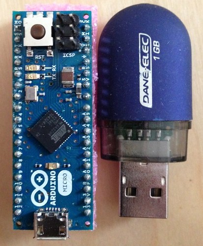
Although I had seen the dimensions of the Micro on the data sheet, the first view of it was still impressive: The entire Arduino board comes in the size of a DIP-34 package (if such a thing existed). In fact, it is smaller than some AVR microcontrollers (like the ATmega1284 shown here).


Among the more difficult consequences of the tiny size of the Micro is that the pin labels can be fairly hard to read for aging eyes like mine, and since they are between the pins, it’s easy to forget which pin they apply to. Several of the first experiments I built had at least one connection made to the wrong pin, though I expect I’ll get used to the labels after a while.

The top of the board also features the USB Micro B connector. While USB Micro connectors are not uncommon, USB Mini is still a bit more prevalent among Arduinos, and the only Micro cable I had around happened to be Micro A. It pays to check in advance and order either the regular USB Micro cable or the Sparkfun Cerberus cable along with the Arduino Micro — otherwise, your friendly neighborhood retailer will be happy to charge you the price of an Arduino Micro for a connector cable!

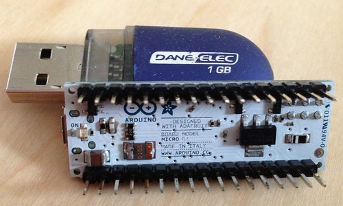
A look at the bottom of the Micro shows that the board has components on both sides; the 34 pins are implemented as fairy sturdy male header pins that work great on breadboards. From the dimensions, I had expected that the Micro would also fit into a DIP-40 socket (e.g. so it could be easily inserted and removed from larger projects), but it appears that the pins are a bit too thick to make this possible without employing excessive force.

High Level Features

From the point of view of the Arduino API (digitalRead, digitalWrite, analogRead, analogWrite), the Arduino Micro is straightforward to use and powerful.

Digital I/O

At first glance, one might think that an Arduino Micro offers exactly as many digital pins as an Arduino Uno. However, the reality is quite a bit better than that:
  • The standard serial port of the Micro runs over USB. A hardware port is available on pins 0 (TX) and 1 (RX), but it is possible to use these pins for other purposes while still maintaining a full serial connection to a computer.
  • SPI is run through a separate set of pins (MOSI/MO, MISO/MI, SS, and SCK), which are available as digital pins if not used for SPI.
So while an Arduino Uno has a maximum of 20 pins available, and only 18 if the serial port is used, an Arduino Micro has 24 pins available. This is, in fact, better even than the Arduino Leonardo, which is largely pin compatible with the Micro, because the Leonardo only makes the SPI pins available through the ICSP header, and does not make the SS pin available at all.
A few extra pins may not seem like much, but as I’m currently working on a problem requiring 19 pins (see below), having 20 pins readily available was just perfect.

Analog Input

The Arduino Micro has a generous 12 analog inputs (6 of which are on “analog” pins, and 6 on “digital” pins).

“Analog” Output

There seems to be a bit of confusion surrounding the number of PWM outputs an Arduino Micro has. While the text on boxtec’s site correctly gives the number as 7, the accompanying diagram has 8 pins labelled as “PWM”. Two of those, 4 and 12, are not usable as Arduino analog pins, and pin 3, which is usable, is not labelled “PWM”. So, for the record, the usable PWM pins are 3, 5, 6, 9, 10, 11, and 13.

Low Level Features

If you like to dig a bit deeper into the mysteries of AVR programming, here are some lower level considerations.

Pin Layout

While digitalRead/digitalWrite are very useful abstractions, it sometimes is helpful to access the underlying port registers directly. In particular, it is sometimes possible to change or read up to 8 pins simultaneously. The precondition for this is, of course, that those pins are part of the same port, and it often helps if the physical sequence of the pins is the same as their bit order in the port.

The standard Arduino layout is pretty good at this, with the 20 pins arranged as one 8 bit sequence and two 6 bit sequences. Unfortunately, the Arduino Micro layout (and the Leonardo layout, on which it is based), is a different story altogether: The 24 pins of the ATmega32u4 are spread across 5 8-bit ports, and due to layout considerations, the Arduino boards rearrange pins and pick the occasional bit in the middle for LEDs. As a result, the longest contiguous sequences available are two 4-bit sequences.

Pin Interrupts

Another difference between the ATmega328 and the ATmega32u4 is that the former has a pin change interrupt available for any input pin, while in the latter (and thus the Micro), only 8 of the pins have pin change interrupts, 4 of which are assigned to the SPI interface. In practice, this should rarely be a limitation, but if you expect to be able to get a pin change interrupt on every conceivable I/O pin, that’s not going to work on a Micro.

Timers

On a happier note, the ATmega32u4 has a very impressive collection of timers:
  • Timer 0 (8 bit) and 1 (16 bit) appear to have fairly similar features across the entire ATmega line.
  • Timer 3 is virtually identical to Timer 1.
  • Timer 2 (8 bit on ATmega328) does not exist on the ATmega32u4.
But it is Timer 4, a 10 bit timer, that is particularly intriguing. It features no fewer than 6 PWM outputs, arranged in 3 pairs: For each PWM output, its complement can also be made available on another pin. A dead time generator can be set to slightly offset the two signals to introduce times when both signals are 0 (or 1), which appears to be useful for some power switching applications. A fault protection input can turn off the PWM outputs quickly. And finally, the timer can be clocked at an internal PLL frequency of up to 64MHz.

Using the Arduino Micro

Uploading Sketches

The Arduino IDE ships with support for the Arduino Micro in the “Board” menu. The upload procedure is a bit different from the Arduino UNO, and in practice, I’ve often found it necessary to manually press the reset button on the board in order for an upload to succeed. 

USB Support

One of the attractions of the Micro is obviously its hardware USB support. The Arduino software supports emulation of a Serial port, a Keyboard, and a Mouse. All three of these seem to work very reliably, and performance can be downright scary: It’s easy to send so much text to the Keyboard emulation that your computer keeps typing for several minutes after you’ve unplugged the Micro.

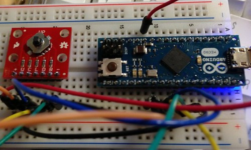
As a proof of concept, I built myself a simple mouse, using a SparkFun 5-Way Tactile Switch Breakout board.


Nevertheless, I found that the Arduino libraries make rather conservative use of the USB hardware capabilities available. For instance, I would find it very useful to open a second USB serial port, and the hardware seems to be capable of doing it, but the libraries don’t support it. There also is no built-in support for other USB protocols, e.g. MIDI over USB. One of my future projects will be exploring third party projects like LUFA, which are supposed to be considerably more powerful. 

High Voltage Parallel Programming

One of my current obsessions (and the origin of my infamous 19 pin problem) is the implementation of the various programming protocols available for AVR processors. I’m in the final testing stages of a new programming sketch named ScratchMonkey, and was eager to play with the Arduino Micro as an alternative to the Uno for a programmer.

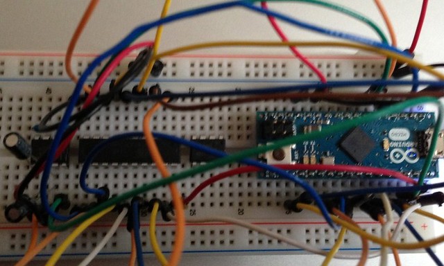
I’m pleased to report that the Micro performed perfectly in this role. The extra pins allowed me to use a simpler breadboard setup (with the Uno, I had to use an auxiliary shift register for the control signals), and after a few minutes of cabling, I was able to successfully reprogram an ATtiny4313:


Shown here, left to right: A Maxim MAX662ACPA+ charge pump IC to generate the 12V high voltage signal from the 5V input; the ATtiny4313 target MCU, an ATtiny85 left on the board from a previous experiment, and the Arduino Micro.

Summary

An Arduino Micro probably should not be the first Arduino to give to a beginner: The small labeling, the finicky upload procedure, and the limited compatibility with Arduino shields are all drawbacks to a certain extent. However, the Micro excels with its breadboard friendliness, its USB capabilities, and a pin count and feature set exceeding most regular size Arduino boards. I highly recommend it as a second Arduino board for owners of a standard Arduino, or as a board for users with previous microcontroller experience.

2013-02-18

Overqualified Flashlight

I had an old plastic flashlight with partially corroded innards, and no incandescent bulbs for it, so I decided to turn it into a fancy RGB LED spectacle, controlled by an ATtiny85.

Power Supply

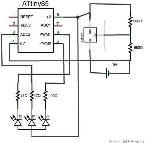
The RGB LED I had needed forward voltages of 3V and more, so keeping the original 2x1.5V C cell power supply was not really viable (apart from the corrosion problem), so I decided to use a 9V battery. However, 9V was outside the operating range of the ATtiny85, so I used a LM317 voltage regulator to adjust the voltage to 3.8V (comfortably within the range of the ATtiny85, close to 3.3V for experiments, and suitable for resistors I had available).

Prototyping & Programming

Breadboarding the circuit was trivial, with my new Bus Pirate serving ably as a SPI programmer. 

Adding the Bus Pirate as a Programmer to the Arduino IDE is simple: In your Arduino projects folder (~/Documents/Arduino on a Mac), add a file hardware/buspirate/programmers.txt:
this will work OK, but quite slowly, as the version of avrdude shipping with current Arduino IDEs includes a suboptimal protocol for talking to the Buspirate. If you download the latest version of avrdude from its subversion repository, recompile, and copy avrdude and avrdude.conf to their corresponding paths in the Arduino IDE, it’s possible to obtain much higher programming speeds (You could also re-flash the Bus Pirate firmware to set it up for the stk500 protocol, but I would not recommend that).

While in earlier ATtiny85 experiments, I used the attiny Arduino cores, I switched to the Arduino-tiny cores this time, because attiny only supported 2 PWM pins on the ATtiny85, while Arduino-tiny supports 3.

The code itself is straightforward, except that since the LED is common anode, it is activated by a LOW output, and by the “inactive” part in the PWM cycle.

Layout

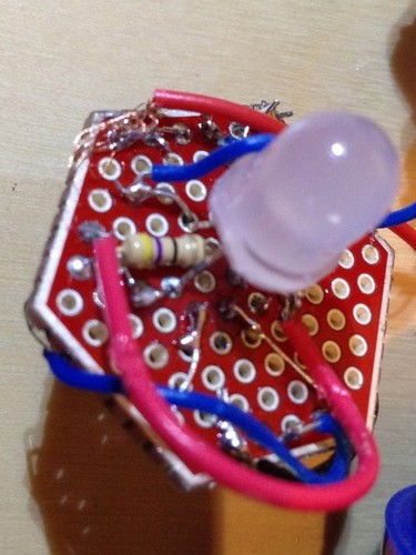
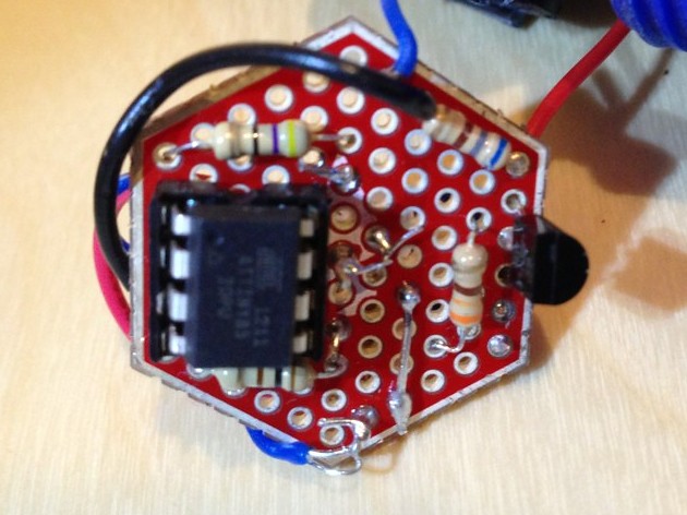
I had a SparkFun hex shaped protoboard that fit the flashlight very well. Fitting all the components onto the board was rather challenging, especially since the position of the LED in the middle of the board was not really negotiable. My original plan was to put the LED on one side and the rest of the components on the other, although this added some additional complications for the wiring.

Assembly

Despite the cramped layout, I thought I had done a pretty good job placing the components. Unfortunately, I had forgotten to include the current limiting resistors for the LED, so the LM317 failed within a few seconds. Luckily, I had a scratch monkey at hand, and the LED and the ATtiny were undamaged. Removing the failed LM317 proved rather difficult, and retrofitting resistors between the LED ATtiny even more so. Ultimately, I found it easiest to put one of the resistors on the LED side of the board.


I wanted to use the existing power switch built into the case, so I had to connect to the power switch, and to the bulb socket, which turned out to be rather frustrating work, so I ultimately cheated by adding some strategically placed aluminum foil:


The Result


2012-12-31

Putting On My Hardware Hat

Recently, my son became interested in LED sneakers, so I pondered making something similar for him, which would be a good opportunity to explore the LilyPad textile friendly Arduino platform. I didn't like the odds of building something robust enough to survive in a shoe, and LilyPads are not all that small, so I decided on building a LED hat (with temperature sensitive LED patterns, to make it interesting).

Materials

Boxtec carries a reasonable selection of LilyPad compatible boards to get started. In particular the ProtoSnap LilyPad development board contains all the electronics used in this project, except for the colored LEDs, and also comes with a 110mAh LiPo battery, the conductive thread needed to connect everything, and an FTDI board for the USB connection (No separate charger for the battery is needed; the battery will charge when the LilyPad is connected to USB).

Pretty much any hat should be OK for this project; the one I picked turned out to be a bit on the small side for the customer, and picking a color so close to the color of the conductive thread was not as clever a decision as I had originally thought.

Layout

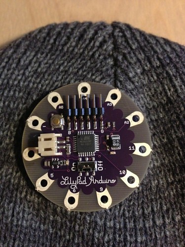
I started out by installing the LilyPad Simple processor board on the inside of the hat, at the very top, and a temperature sensor on the outside, at the top (The temperature sensor is not currently used, although I got it to work to some extent; more on this in a separate post).

LilyPad Simple board with hat

The LEDs are arranged in two staggered rings of 4 LEDs each, red on top, and alternating blue/green on the bottom.

Sewing the Connections

This was the true challenge in this project. I may have learned a little bit of sewing as a child, but hadn't held a needle in more than 25 years. However, this Instructable on Sewing was quite helpful, and entirely sufficient to get the project done.

Initially, I started with a planned pin assignment for the LEDs, but it turned out to be easier in some cases to stitch a connection from whatever pin was closest to the LED I wanted to connect, and adapt the code to the physical layout, rather than the other way around. Since I was not using PWM, and only one analog input, most pins were largely interchangeable for my purposes.

Writing the Code

My plan was to run the red LEDs and the blue&green LEDs separately, so I could have one LED in each group lit. To save pins, I wired up the red LEDs using a Charlieplexing scheme using 3 pins. However, when testing the result, one of the LEDs would not work cleanly, with two of its neighbors lighting up as well. Despite testing all the connections for short circuits, I was unable to find the cause. I suspected that the high impedance state might not have worked as planned, due to the peculiarities of LilyPad connections.

To test this, I wired the blue/green LEDs using 4 pins, with a simpler multiplexing scheme that did not rely on tristate logic. Ultimately, though, the results were not much better, with one of the LEDs never lighting up. I probably would have been best off with a common cathode/anode, one pin per LED scheme, but for what it's worth, my code is here.

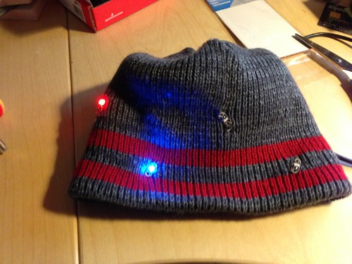
Hat with blinking LEDs

Tying up the Loose Ends

Having decided that my result was close enough to what I wanted to build, I installed the battery in place with some non-conductive thread.

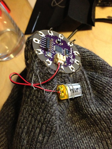
Battery sewed in place on hat
(Visuals like this are why it may be inadvisable to take homemade electronics through airport security).

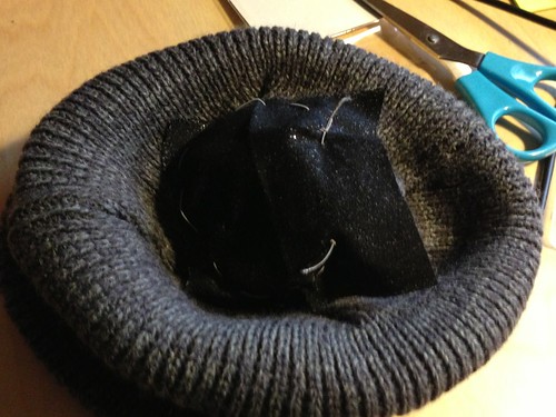
Finally, I wanted to cover up the LilyPad main board and the battery. Having the electronics in contact with someone's head seemed like a bad idea for the electronics, and the LilyPad has a rather prominent male 6 pin connector, which looked like an injury risk. A piece of black repair sheet, and some more non-conductive thread did the job reasonably well (with the opening of the stitching leaving enough space to insert the FTDI/USB board for reprogramming and recharging).

LilyPad board covered with repair sheet stitched into place

Customer Test

After some initial skepticism, my son decided that his hat was nearly as cool as a pair of LED sneakers:


Lessons Learned


  • Working with conductive threat is the equivalent of building a circuit using non-insulated wires exclusively. It can be tricky to avoid short circuits.
  • My idea of having most of the stitching run between the outer and inner layers of the hat made it even harder to find out what’s going on.
  • It’s not clear whether the material of the hat might have been somewhat conductive itself.
  • Redoing a stitched connection can be quite a bit more work than redoing a wire, especially since I tried to run a single thread through several destinations, instead of doing strictly point to point connections.
  • That said, the stitching itself was not terribly difficult, as long as I was not overly fussy about the esthetics of the outcome.


2012-08-13

Foca 2.1 as AVR ISP

Turning a Misunderstanding into Reality

Recently I started dabbling in ATtiny programming, and I became tired of tying up my Arduino UNO as an ISP, so I wanted a standalone ISP.

The Foca 2.1 board seemed to fit the bill. The product description mentioned it being a "Programmer for Arduino and compatible boards", and the data sheet showed a familiar looking 6 pin header in the "ISP Zone", so I bought the board from Boxtec.

Only when I started playing with the board did I realize that the 6 pin header simply was breaking out control pins for an RS232 serial interface, and that the "Arduino Programmer" was meant to program ATmegas with boot loaders through the serial port, not bare ATtinys through the SPI based in-system chip programming interface.

Enter Plan B

However, the FT232RL chip on the Foca board is very flexible, and supports a "Bitbang" mode, in which the data sent directly sets 8 control lines to arbitrary values, instead of being sent through a serial interface. Support for SPI based in-system chip programming was already in the avrdude SVN repository (though not in a release yet).

Dude, where's my AVR?

Checking out the latest version of avrdude from its SVN repository, I initially had little success getting the ftdi_syncbb method to work.

This turned out to be mainly due to the fact that OS X has linkable stubs for anonymous semaphore functions (sem_init, etc.), but actually returns errors from them. Code that does not check these functions for errors (like the ft245 code in avrdude) becomes wildly susceptible to race conditions. 

After fixing this problem, the code worked, but only at very slow bit rates (2400 or less). While better than nothing, this was rather disappointing performance, and at faster rates, scary things like reprogrammed fuses happened.

Faster, SPI! Kill! Kill!

A Technical Note from FTDI suggested a reason for my problems: The data in bitbang mode was written based on a clock that was not synchronized to the data clock, so signal pulse widths were not reliable. The suggested remedy was to pad out the data.

So I modified the writing code to write each data byte 4 times, and upon reading, only use every 4th byte (2x duplication helped as well, but beyond certain bit rates still failed). Despite having to write much more data for each bit (effectively 8 bytes per bit), thanks to the improved reliability, I now achieved data rates of more than 45000 bits per second, more than enough to program an ATtiny at blazing fast speeds.

Tweaking the Arduino IDE

Now that I had a working avrdude, all that I needed to do to get it working directly from the Arduino IDE was to copy the binary and the configuration file into the Arduino app, and to create a "programmer" entry in the hardware subfolder of my sketch folder.

Show me the code!

For those interested, the patches and detailed instructions are available in this archive.